Introduction
A small video management system can absorb a lot of configuration mistakes. Past a few hundred cameras, it stops absorbing them. Recording gaps appear during busy playback hours. Video walls stutter when operators switch layouts. Exports slow down just when an investigation needs them.
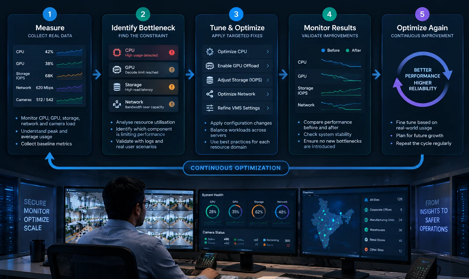
VMS performance tuning at this scale starts with knowing where the load lands. Four resource domains carry almost all of it: CPU, GPU, storage IOPS, and network. Each fails in its own way, and a change in one usually moves load onto another. For system integrators and security architects, the working question is which constraint is binding right now.
Understanding the load profile of a 500+ camera VMS
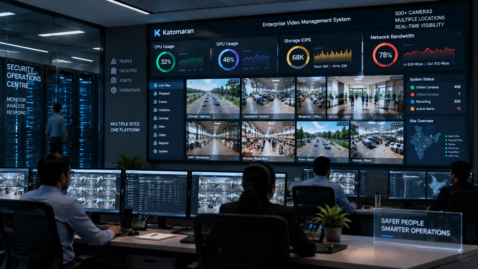
A large VMS runs several workloads at once, and they behave very differently.
Continuous recording - Steady, write-heavy, and mostly predictable. It usually accounts for the largest share of storage and network traffic.
Live viewing - Bursty and tied to operator behaviour. A video wall with many tiles creates heavy decode load on the client, or on the server if streams are transcoded.
Playback and export - Random read load on storage that competes directly with recording writes.
Event and forensic search - Queries against metadata and indexes, and in some systems, scans across recorded video. This puts pressure on the database and its storage.
Analytics handoff - Analytics engines pull streams from cameras or from the VMS, which adds network sessions and, in many designs, decode work.
Multi-user access - Each client session can pull its own streams and trigger transcodes.
The load is also uneven. Cameras covering a busy gate produce far more bitrate under variable bitrate (VBR) encoding than cameras facing an empty corridor. Night scenes with infrared noise can push bitrate well above daytime levels. And a single incident changes everything at once: several operators open the same cameras, pull hours of playback, and start exports while all recording continues.
Size for the incident, because a system sized for the average day will struggle during one. If you are mapping these workloads onto recording, management, and client layers, our overview of VMS architecture for large enterprises walks through how those layers separate.
CPU bottlenecks
What drives CPU usage
Recording by itself is light on the CPU: the server writes the compressed stream to disk without decoding it. CPU cost climbs once the server has to look inside the video.
The main CPU drivers in a large VMS are:
Server-side motion detection, which requires decoding every stream it evaluates
Transcoding for mobile clients, web clients, or low-bandwidth remote sites
Metadata and event processing, including rule evaluation and database writes
Concurrent client sessions, particularly when each one requests a transcoded stream
Encryption of streams and management traffic at high session counts
Common symptoms
Dropped frames or recording gaps logged against specific cameras
One or two cores pinned at full load while the average looks acceptable, which points to a single-threaded process
Growing event queues and delayed alarms
Performance that degrades during warm afternoons, a sign of thermal throttling in server rooms without adequate cooling
Practical tuning approaches
Move motion detection to the camera where it is reliable: Many cameras can generate motion events or metadata themselves. If the VMS consumes those events, it does not need to decode every stream to decide what to record.
Use multi-streaming deliberately: Record the high-resolution main stream. Serve a lower-resolution sub-stream to live grids and small tiles. Configure clients to switch to the main stream only when a tile is enlarged.
Separate recording from live view: Dedicated recording servers should do little else. Place transcoding and mobile gateway services on separate hosts so a surge of remote viewers cannot starve the recording service.
Limit transcoding: Serve direct streams on the local network where clients can decode them, and apply transcoding limits by role.
Balance by bitrate: Two recording servers with equal camera counts can carry very different loads. Distribute cameras by measured bitrate and keep headroom on every server.
Set process priority and power profiles: Give the recording service the highest priority, and use a performance power profile in the operating system and BIOS.
Weigh codec choice carefully: H.265 reduces bitrate compared with H.264 at similar quality, but it costs more to decode. The saving on storage and network can reappear as CPU load on servers and clients.
GPU considerations
When GPU offload helps
A GPU earns its place when a large share of the load is decode, encode, or inference:
Client workstations and video wall controllers decoding many streams at once
Servers that transcode continuously for remote or mobile users
Analytics workloads running deep learning models on live video
When it does not help
Pure recording. With no decode, there is nothing for the GPU to do.
Storage or network constraints. A GPU cannot fix slow disks or saturated uplinks.
Database and search latency. These are usually storage and query problems.
Unsupported codec profiles. If the hardware decoder does not support a camera's codec or profile, the VMS may fall back to CPU decoding without an obvious warning.
Some GPUs also cap the number of concurrent encode sessions, which matters for transcoding servers.
Decoding and analytics are different workloads
Video decoding runs on fixed-function media blocks inside the GPU. Analytics inference runs on the compute cores and depends heavily on GPU memory. When both share one card, they compete for memory, and memory usually sets the ceiling on how many streams the card can handle. Keeping both on one card does keep frames in GPU memory between decode and inference, which avoids extra copies.
When to introduce GPU resources
Add GPUs when measurements show decode or transcode consuming a large share of CPU on specific hosts, or when analytics moves beyond simple camera-side rules. Before buying, confirm four things: the VMS supports hardware decode for your codecs and profiles, the drivers are supported on your operating system image, your monitoring can read GPU decode and memory usage, and the power and cooling in the rack can take the extra load. For analytics-heavy designs, our AI video analytics services page covers how analytics workloads connect to the VMS.
Storage IOPS and throughput
Capacity and IOPS measure different things
Capacity tells you how much video fits in the retention period. IOPS and throughput tell you how many reads and writes the storage can complete per second at acceptable latency. An array can hold the full retention period and still fall behind on writes.
This matters more as drive sizes grow. On spinning disks, per-drive IOPS stays roughly the same regardless of capacity. Buying fewer, larger drives to reach the same capacity reduces spindle count, and with it, the IOPS available to the recording service.
What shapes storage load
Recording format and bitrate: Hundreds of concurrent streams, each written in small chunks, look much less sequential to the array than a single stream does. File system metadata updates add further random I/O.
Retention: Longer retention needs more capacity, and deleting expired footage creates background I/O. If that job runs during busy hours, it competes with recording.
Simultaneous playback: Playback produces random reads that contend with writes on the same volumes. Incidents cause sharp spikes.
Forensic search: Index and metadata queries slow down badly when they share disks with video writes, and they can slow recording in return.
RAID rebuilds: Rebuilds on large drives take a long time, and the array runs degraded throughout. Recording must still keep up during that window.
Common storage design mistakes
Sizing on terabytes alone
Placing the operating system, VMS database, and video on the same volume
Sizing on average bitrate and ignoring peak VBR bitrate
Using desktop-class drives that are not rated for continuous multi-stream writes in multi-drive enclosures
Assuming file-share protocols will behave under hundreds of streams the same way they do under a few dozen, without testing
Leaving no headroom for rebuilds or camera growth
Practical recommendations
Put the operating system and application on their own drives, and place the database and indexes on SSD.
Keep video on dedicated arrays, spread across multiple volumes so no single volume carries all the writes.
Use a hot tier for recent footage, where most playback happens, and a larger archive tier for older footage. Schedule archiving and deletion outside peak hours.
Test storage performance with the RAID set degraded as well as healthy.
Use surveillance-rated or enterprise drives, and monitor drive health continuously.
Network bottlenecks
Bandwidth calculation at scale
The basic calculation adds up the bitrate of every stream on each network path. The hard part is counting paths and streams correctly. A large VMS carries traffic from cameras to recorders, from recorders to clients, from recorders to archive storage, and, in multi-site designs, from each site to a central location.
Several factors push real traffic above calculator estimates:
VBR peaks from busy scenes, rain, and night-time noise
Protocol overhead and retransmissions
Several consumers pulling separate streams from the same camera, such as the VMS, an analytics engine, and a failover recorder
Uplink oversubscription at aggregation switches, where many camera ports feed a single uplink
Measure actual camera bitrates over a full day, including night hours, and design for peak with headroom. For estates spread across locations, our guide to multi-site VMS centralization covers how WAN links shape the design.
Multicast and unicast
With unicast, each viewer receives its own copy of a stream. It works across routed networks, WAN links, and firewalls, but load grows with every additional viewer.
With multicast, the VMS or camera sends one stream to a multicast group address, and any number of receivers on the local network can join it. This suits control rooms and video walls where many displays show the same cameras. It needs careful switch configuration: IGMP snooping to stop switches flooding the traffic to every port, and PIM if the traffic must cross routed segments. Multicast is usually a poor fit for remote clients, WAN links, and cloud-connected viewers.
Camera stream configuration
Camera settings have a direct effect on the network:
Resolution and frame rate set the baseline bitrate.
Bitrate mode: Constant bitrate is easy to plan for but wastes bandwidth on quiet scenes. Capped VBR gives a predictable ceiling with lower average traffic.
GOP length: Longer intervals between I-frames reduce bitrate, but playback seeking slows because the decoder must start from the previous I-frame.
Smart codec features: These can lower bitrate considerably on static scenes. Test them for image quality and seek behaviour before rolling them out across the estate.
Segmenting traffic
Place cameras, recording servers, operator clients, and management interfaces on separate VLANs.
Give recording servers separate network interfaces for camera ingest and client delivery.
Keep iSCSI or other storage traffic on its own network.
Apply QoS so live view for operators takes precedence over bulk export or archive transfers.
A system-level tuning approach
Bottlenecks in large VMS deployments rarely appear on their own. A setting change in one place usually shows up in all four resource domains. The table below shows how common changes spread.
How Common Configuration Changes Impact VMS Resource Domains
| Change | CPU | GPU | Storage IOPS | Network |
|---|---|---|---|---|
| Higher recording resolution | More decode load for live view and motion detection | More decode load on client stations | More write throughput and capacity | Higher bitrate on camera and client paths |
| Moving from H.264 to H.265 | Higher decode cost per stream | Depends on hardware decoder support | Lower write throughput | Lower bitrate |
| Adding server-side analytics | Decode load if not offloaded | Inference and decode load | More metadata and index writes | Additional stream pulls from cameras |
| Serving live grids from sub-streams | Lower decode load on clients | Lower decode load | No change to recording | Lower client-path traffic |
| Longer retention | Larger indexes to maintain | No change | More capacity and more deletion I/O | More archive transfer traffic |
The working rule is to change one variable at a time and measure all four domains afterwards. Keep a baseline from before the change, including one captured during a busy period.
Monitoring and diagnostic practices
Metrics that matter
CPU
Per-core utilization alongside the average
Run queue length
Thermal throttling events
GPU
Decode and encode utilization, tracked separately from compute utilization
GPU memory usage
Active encode and decode sessions
Storage
Read and write latency
IOPS and throughput
Queue depth
RAID state and drive error counts
Free space trend against the retention target
Network
Interface utilization at peak times
Packet drops, discards, and retransmissions
Multicast group membership where multicast is used
VMS level
Recording gaps and dropped frames per camera
Stream reconnect counts
Actual camera bitrate compared with configured bitrate
Event queue length and alarm delay
Export completion time
Conclusion
Performance in a 500+ camera VMS comes from architecture and configuration discipline applied across CPU, GPU, storage, and network together. A faster server helps only when the server is the binding constraint, and in large estates the constraint moves as cameras, users, and retention change. Measure each domain, understand how a single setting spreads across all four, and size the system for its busiest hour.
If you are planning a large camera estate or reworking an existing one, you can explore how Katomaran's Video Management System handles recording, playback, and multi-site operations, or compare deployment models in our VMS vs VSaaS guide. Our team is also available to talk through sizing and architecture for your environment.
Frequently Asked Questions
What is VMS performance tuning?
VMS performance tuning means finding the resource that limits a video management system and fixing it through configuration or architecture. I examine CPU, GPU, storage IOPS, and network together, since fixes shift load between them.
Why do VMS bottlenecks appear in 500+ camera environments?
At that scale, recording, live viewing, playback, and search all compete for the same servers, disks, and links. Small inefficiencies multiply across hundreds of streams. An incident then pushes every workload up simultaneously.
Does a large VMS need GPUs?
Only for specific workloads. I recommend GPUs when measurements show heavy decoding on client stations, sustained transcoding, or deep learning analytics. Pure recording gains little, because servers write compressed streams without decoding them.
How is storage IOPS different from storage capacity in a VMS?
Capacity decides how much video you can keep. IOPS decides whether the array can write hundreds of streams and serve playback without lag. We size for both, and we test performance during RAID rebuilds.
Should a large VMS use multicast or unicast?
Multicast works well where many local displays show the same cameras, such as video walls, provided IGMP snooping is configured. Unicast suits remote clients and WAN links. Most large estates use both, chosen per path.

Caldwell Simon
Project Manager
Caldwell Simon, Project Manager at Katomaran Technologies, writes on AI video analytics, VMS, IoT integration, and large-scale surveillance deployment and delivery.